
How to connect a servo driver
Introduction
This blog explains more about connecting a servo drive to our controllers. In this example, we use a Delta ASDA-B3M Series.
Although the information is based on a B3M drive, it should still be helpful for anyone who wants to understand the basics of connecting a similar drive.
First, a disclaimer. Although all information in this document has been put together with care, it’s always possible that we made a mistake. So, the information is presented as-is, and it’s essential to make sure you understand all the information yourself. Using the information described here is ‘at your own risk’.
Reading the manual
Step 1. Check if the drive supports step and direction signals.
The first step is to look in the drive’s manual and find what kind of interface it is available. In this case we find this overview in the manual:
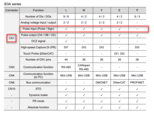
It supports the controller step and direction signals, which are called Pulse and Sign. The signals can be found on connector CN1.
Step 2. What kind of step and direction signals does it accept?
Besides that, it accepts step and direction signals, there are still things to check:
- What are the voltage levels
- What is the frequency of the step signal
- Does it support single-end or differential signals
Let’s explain the difference between single-ended and differential signals.
Single-ended and differential signals refer to how control signals are transmitted from the controller to the driver and motor. Choosing between these signaling methods affects noise immunity, signal integrity, and performance.
Single-Ended Signal
A single-ended signal uses one wire to transmit the signal and a common ground as the reference.
Advantages:
- More straightforward wiring and lower cost.
- Works well in low-noise environments over short distances
Disadvantages:
- More susceptible to noise: Any electrical interference can distort the signal since the reference (ground) may not have the same potential throughout the system.
- Voltage drops: Over long cables, signal integrity can degrade.
Differential Signal
A differential signal uses two complementary wires to transmit the signal. Rather than referencing a ground, the receiver reads the difference between the two wires.
Advantages:
- High noise immunity: Since both wires pick up noise equally, the interference cancels out when the difference is measured.
- Better signal integrity over long distances: Used in industrial environments where electromagnetic interference (EMI) is high.
Disadvantages:
- Requires extra wiring and differential receivers, increasing complexity and cost.
In summary, differential signaling is superior in noisy or long-distance applications, while single-ended signals are more straightforward but more prone to noise issues. Modern servo drives use differential signaling for critical signals like encoder feedback and communication.
So let’s find an overview of the signals:
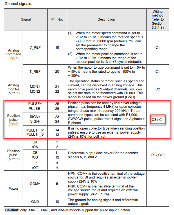
This overview shows that it accepts different kinds of input signals. It accepts a line-driver signal (differential signal) and an open-collector signal (single-ended). It also indicates that the line-driver signal can be up to 4MHz single, but the open-collector signal can not be higher than 200kHz. The 200kHz limit is essential when using a controller that can supply a higher step frequency than 200kHz, for example, the CNC7xx series. The picture also shows what wiring methods can be used, C3/C4.
When you use a controller that can generate a higher step frequency, you should adjust the setup of our software to lower this frequency.
Step 3. Check what the signals levels are that are accepted.
We can look at wiring methods C3 & C4 to learn more about this:
Method 1. Single-ended signal
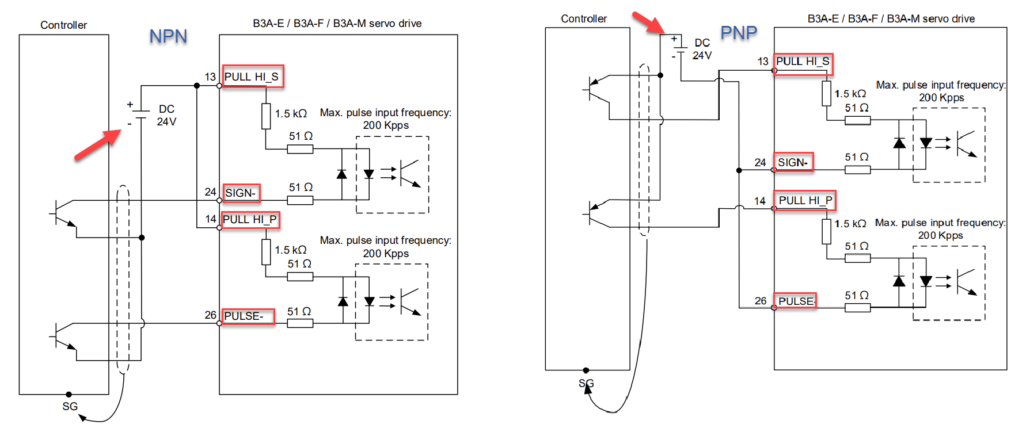
This picture shows two ways of controlling it: through an NPN or PNP signal. This refers to whether the controller switches the ground (negative) or the +24V (positive). The manufacturer indicates that the PULL HI_P and PULL HI_S are required. Also, it is repeated that this signal has a maximum of 200kHz.
Method 2. Differential signal
The second method is a differential input signal as shown below:
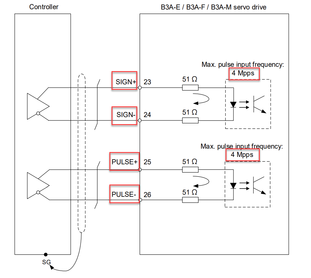
The picture clearly shows that SIGN+/- and PULSE+/- are used for a differential signal. Remember, SIGN corresponds to our DIRECTION signal, and PULSE corresponds to the STEP signal. It also shows that this input signal frequency can go up to 4MHz.
Method 3 ?
Besides these two methods, there is a potential third option. However, this depends on the maximum input level of the signal. Some controllers supply a 5V step/direction signal. Connecting this +5V output signal to the + input and the – input to ground could work…BUT…check the signal levels. For this drive the manufacturer states:
Pulse input (differential line driver input) can only be used with 2.8V – 3.6V power systems.
In this case, connecting a +5V signal to this input would not be possible since this can damage it.
Controller output signals
In the table below is an overview of the output of our controllers:
- CPU5A4(E) : output 5V, max. 125kHz
- CNC530 : output 5V, max. 125kHz
- CNC720: output 5V, max. 400kHz
- CNC760 standard: output 5V, max. 400kHz
- CNC760 line-driver: output differential 3.6V, max 400kHz
- CNC600: output open-collector, max. 125kHz
Conclusion
I hope that this information will help you determine whether the servo drive you would like to use is an option.


